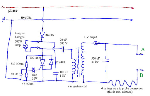
and one more mistake...
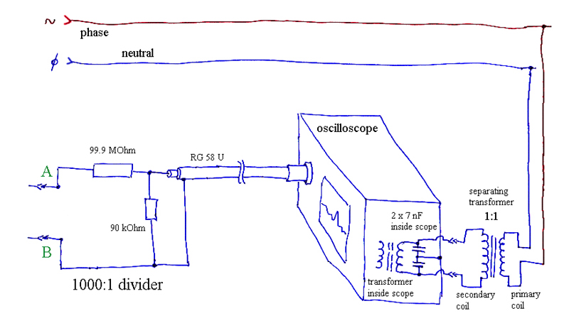
I was make one little high voltage (resistor) divider 1000:1 and trying to see how looks pulse at
one HV pulser with my oscilloscope. Because I was hurry too much, creep one BIG mistake.
After few successful observing at oscilloscope of various points at HV pulser, I got
idea to make "pulse sharpener" with capacitor, spark gap and load. As load, I was put
resistors, capacitors, and finally coil...
But then happened something what I was not expect: transformer of 500 VA with ratio
of 1:1 which I always use for separating oscilloscope from power line begin burn.
This transformer is there because few times I was got power line phase at ground of
oscilloscope, and fortunately nothing was happened at this time. But for prevent another
similar situation I was make decision that this transformer need to be there.
Later I was make little investigation what was wrong and found answer, but first
I need to show to you few successful measurement with oscilloscope, and how
looks this 1000:1 divider:
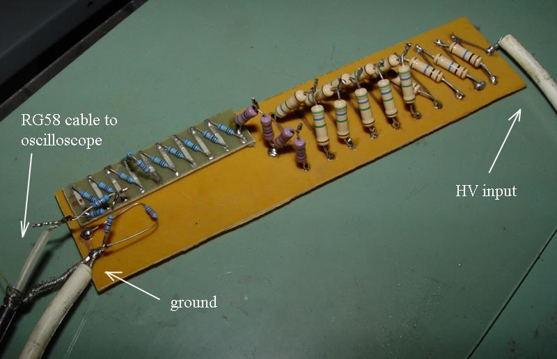
This divider consist many various resistors, because I was not found one of 99.9 MOhm and one of 90 kOhm.
Even, sometimes is hard to found resistors of 10 MOhm, like at this picture, so I was combined few other.
Now, how look connections between voltage divider and oscilloscope:
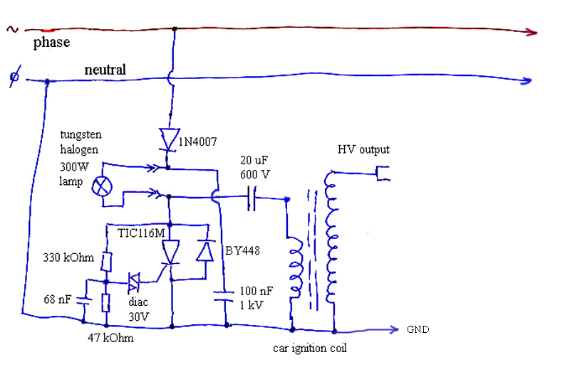
And HV pulser (50 pps, 30 - 35 kV output):
Because I have only one old 15 MHz oscilloscope "Volcraft 2020", it have some
trouble with negative pulse synchronization, which make very difficult to see right pulse
duration and pulse rise time, I was use it's "magnifier" x 5, but sometimes it is not enough.
And, because this oscilloscope haven't "memory" for observing only one pulse, I was
use pulser of 50 pulses per second (pps). Next picture is without this magnifier:
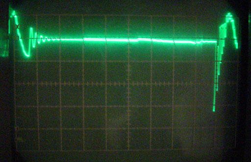
(horizontal 2 milliseconds/div, vertical 10 kV/div)
Now picture with magnifier x 5 and how looks right shape of pulse of previously image:
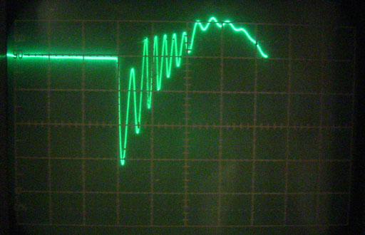
I was try to make measurement with 100 uS/div, but you will see how this is difficult:
(horizontal 100 uS/div)
Before transformer burn, I was make few successful measurement:
 |
 |
 |
|
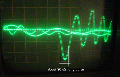
| Primary coil have ~ 80 uS first
negative pulse with peak of -300 V. (I can only speculate about rise
time of about ~ 40 uS) Other pulses are due to self inductance. |
Secondary coil have same pulse
duration of ~ 80 uS and with first negative pulse of about -30 kV (depend of power line voltage which always vary) |
Well, I was forgot adjust "zero" voltage point at same line of screen...
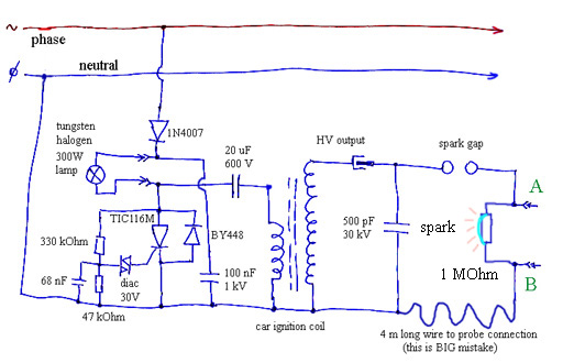
When I was got idea about "pulse sharpener" this looks like in next few pictures:
 |
 |
 |
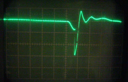 |
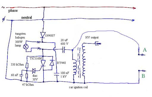
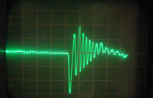
| At diagram you can see my big
mistake, which will later explain why. Now, with added capacitor of 500
pF/30kV parallel to secondary coil, I was observe "little" longer pulse
of about 250 uS, and with rise time of about 120 uS. (only speculations) Load in this time was only divider - 99.99 MOhm. |
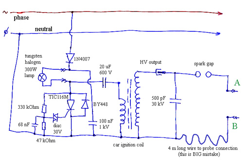
After added spark gap, I was got
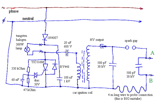
exactly what I was expect - sharper rise time, but not shorter pulse duration like before added capacitor and SG. One "little" odd curve before spark occur is due to capacitance of spark gap which I don't want. Next idea is that maybe one better load of 1 MOhm will compensate this phenomena. Or capacitor of 500 pf. |
I was put one resistor of 1 MOhm with too short distance between resistor's connections
and later was remove it and put there 500 pF/30kV capacitor between point "A" and "B":
 |
 |
 |
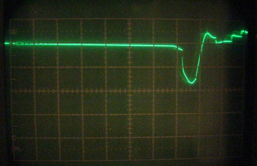 |
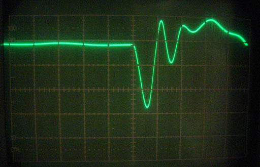
| Because of too short distance
between connections of resistor, I was got this shape at screen (spark
over resistor's surface). About 8 kV pulse across resistor. |
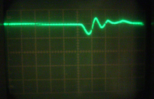
With capacitor was got only
little suppressing odd shape before spark occur. Firstly rise time was
good, but later looks like again 250 uS of pulse duration. And voltage
was drop to half of input voltage before spark gap. |
Connected to this case of too short distance between resistor's connections
I was took some picture:
Resistor not burn, but have two craters on it's body:
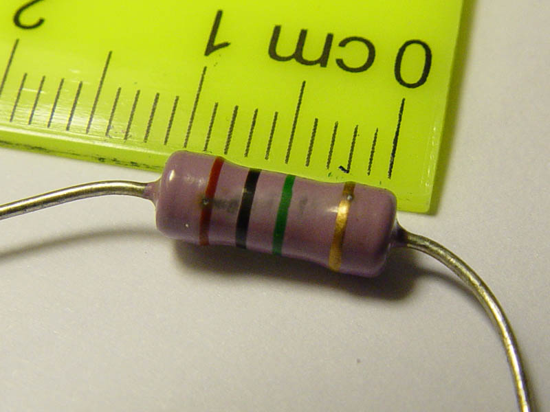
Distance between two of this craters is about 6 mm, and oscilloscope show ~ 8 kV pulse.
After this mistake, I was connect three resistors of 1 MOhm in series (3 Mohm together) but
with same results as in case with load of 99.99 MOhm. Next step is put coil between points
"A" and "B", but then all go wrong.... :o(
What was I expect:
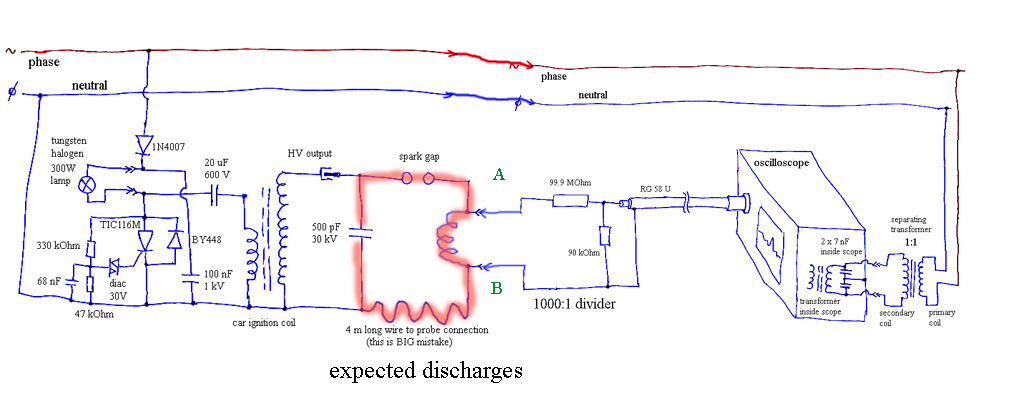
I was expect discharges only as this diagram shown, but instead got next situation:
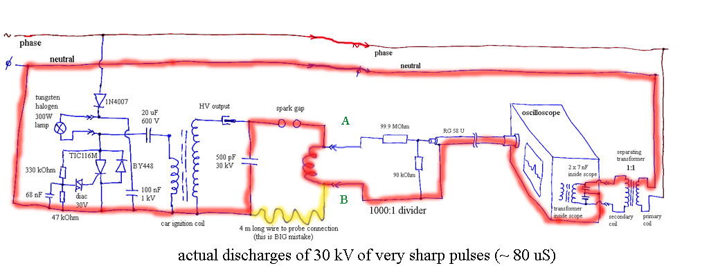
Only part of discharges was dissipate through 4 meter long wire, but this is too long and it
represent something like another suppresser coil. Rest of sharp pulse go around between
neutral power line and through "ground" line which is connected to oscilloscope, and later
through two inner capacitors to insulating transformer which rapidly burn. Transformer
not make any "bang" noise, just fire at bottom of primary coil and I saw flame, and few
sparks of melted metals. Then fuse in home burn, and I stay in dark. :o(
How now looks this transformer now:
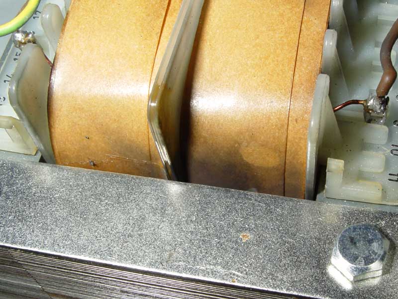
At paper insulation I saw carbonized area, which mean that sharp pulsed spark occurred
firstly from coil to metal of transformer, and then this coil shorted it's wire and make fire.
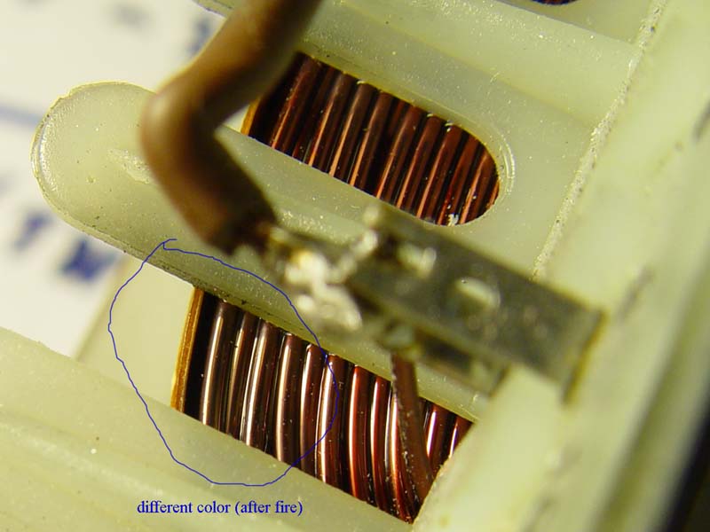
Coil winding at primary at one place slightly change color:
Now, this transformer is ready for reparation.
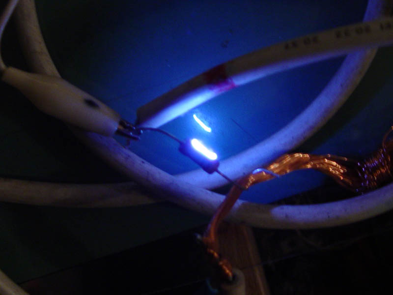
Now, two "bonus" pictures. One of spark gap in "action", and one with result of long sparking time at
metal surface of Chrome-plated metal:
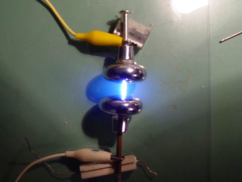
Nice sparks. But,... see:
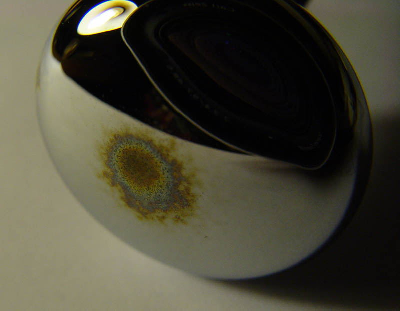
Chrome-plated electrode change it's color due to strong discharges (well, not too strong, but strong enough).